In this posting, I will be discussing how common sources of extreme EMI in a building (such as air-conditioners, elevator motors, generators, radio transmitters and welders) can cause video signal problems when using a CATx extender.
Strong electrical and magnetic fields can cause one electrical device to affect another. When this is unintentional, it is known as electromagnetic interference, commonly abbreviated as EMI.
Normal levels of EMI such as those generated by computers, switches or routers will not affect NTI KVM and video extenders. However, extreme levels of EMI in an installation environment can cause signal and video quality loss when using a twisted pair cabling infrastructure. The longer the cable and the less attention paid to cable installation, the more likely EMI will occur.
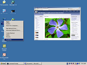
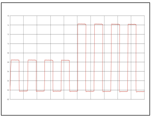
EMI affects both audio and video signals. In audio signals, it obscures low level detail and ambient information. In video signals, the interference distorts the signal and is manifested in different ways. Figure 1 shows an image with no interference. Figure 2 represents a video signal waveform with no interference.
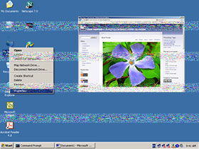
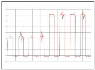
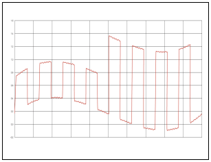
Noise from sources such as air-conditioners, elevator motors, generators etc. is manifested as lines of noise or spots, as shown in Figure 3. This is caused by the electric and magnetic fields generated in the motor as it is running. The larger the motor, the larger the electric and magnetic fields will be. Rapidly turning the motor on and off can also cause interference. Figure 4 shows a video signal waveform with interference from a motor.
A torn and distorted image as shown in Figure 5 is caused by running the cables in the vicinity of sources of strong magnetic fields such as large power transformers and fluorescent lights. The cables have to be in close proximity (less than 1 foot) of fluorescent lights for interference to occur. Figure 6 depicts a video signal waveform that is affected by a large magnetic field.
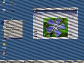
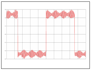
A visible pattern of interference lines as shown in Figure 7 is the result of interference from sources such as radio transmitters. The radio signal needs to be strong and nearby for it to interfere with the video signal being transmitted on a twisted pair cable. Figure 8 shows a video signal waveform with radio transmitter interference.
In a future posting, I will be discussing how shielded twisted pair cabling can help reduce EMI problems.

