Weak Points in Data Center and POP Environmental Monitoring

In Posted in Insight | Tagged | Leave a comment

Extending 1080p HD Audio/Video Using Existing CAT6 Wiring

Whether you are installing a new entertainment center or home theater system, or modifying an existing one, the question always remains about the best way of setting it up. With so many options for connecting devices to one another, it can get complicated fairly quickly, often leading to the dreaded “rat’s nest” of hidden cables as new devices are added. If you have to remove a component from the system, or move the system to a new location, it can be a nightmare to untangle.

Depending on the installation, you may want to locate certain devices in other locations, which may require running additional cable, adding to the frustration and overall cost. One solution to this problem is using the wiring that may have been pre-installed in the walls. This looks much nicer and allows you to locate a media device in another area, such as in a closet or basement. You can then locate the display in an otherwise difficult location that has existing wall wiring access without the expense and headache of new construction.

If you have CAT6 wiring pre-installed, our XTENDEX HDMI Extender via One CAT6 may be the perfect choice to run your high definition video from a source located up to 300 feet away. The HDMI extender requires just one CAT6 cable, and is available with optional IR control. To control the source from the display, simply attach the IR emitter and IR receiver to the extender units, and you’ll have full source control from another room with very little effort.

Installing the XTENDEX extender system is easy with pre-existing CAT6 wiring: to install the transmitter, plug it into the source with an HDMI cable, and connect it to the wall plate with a CAT6 patch cable. To connect the receiver to the system, plug it into the wall plate at the display location with another CAT6 patch cable, and connect it to the display with a HDMI cable. The small size of the extender boxes allows you to hide them easily, and only one power supply is needed to power both units.

For best results, the two wall plates should be directly connected to one another with no other devices connected, the wiring type (and all RJ45 connection points including wall plates) should be rated to CAT6 or better, the cable distances should be kept as short as possible, and the connections should be wired according to the TIA/EIA-568B specification. The desired resolution/color bit depth will determine the maximum extension distance. For more information on maximum extension distances, view the chart on http://www.networktechinc.com/cat6-hdmi-ir.html

Posted in Application Note, Insight | Tagged , , , , , | Leave a comment

Enviromux GSM-USB

This blog is to introduce you to our latest product offering, the ENVIROMUX GSM-USB. The GSM-USB can be used with the ENVIROMUX SEMS 16, the IPDU-S4,

Posted in Application Note, Product Announcement | Tagged , , , , , , | Leave a comment

NTI SNMP Plugin for Nagios

Nagios is an open source network monitoring tool that you might already be using or are familiar with. You can use it to receive Enviromux alerts. By using Nagios, you can monitor ENVIROMUX and your other network devices through the same interface.

Installing the Plugin
Plugins are usually installed in the libexec directory of your Nagios installation (i.e. /usr/local/nagios/libexec). Simply copy the plugin (check_nti_snmp.pl) to the libexec directory of your installation. Be sure to change its permissions to match those of the other plugins.

Configuring a Nagios Command
To add a Nagios command that calls the script, you must add the contents of Listing 1 to your Nagios configuration. The simplest method is to add the contents of Listing 1 to the file commands.cfg, which is often found in /usr/local/nagios/etc/object/commands.cfg.

Listing 1
# Command definition for Network Technologies Inc SNMP plugin
 define command{
       command_name    check_nti_snmp
       command_line    $USER1$/check_nti_snmp.pl -H $HOSTADDRESS$ $ARG1$
       }

Generating a Product Configuration
To monitor NTI products with the NTI SNMP plugin for Nagios, you should first use the script to assist in generating a proper configuration. Using the script to generate the proper configuration greatly eases the burden of deciphering the MIB, interpreting sensor values, etc. View Listing 2 for example.

Listing 2
root@dev:/usr/local/nagios/libexec# ./check_nti_snmp.pl -m config

The script will then ask for some information required to generate a configuration, such as product type, IP address, and SNMP community string. The script can generate two types of configurations: one service for the entire device, and one service for each sensor. Generating one service for the entire device will create a single service entry in Nagios in which all sensors on the unit will be queried. Generating a service for each sensor will allow you finer grained control over which sensors are queried. View Listing 3 for example.

Listing 3
What product type are we configuring for Nagios?
        1) ENVIROMUX-MINI
        2) ENVIROMUX-SEMS-16
        3) IPDU-S2
Enter choice [1]: 1
Enter the IP address of the device: 192.168.1.100
Enter the SNMP community string [public]: public
Which type of service to generate?
        1) One service for the entire device
        2) One service for each sensor
Enter choice [1]: 1

After entering all requested information, the script will generate an appropriate configuration based on your input and print it to the screen. View Listing 4 for example.

Listing 4
# You need to define this command exactly once to monitor NTI products.
# define command{
#       command_name    check_nti_snmp
#       command_line    $USER1$/check_nti_snmp.pl -H $HOSTADDRESS$ $ARG1$
#       }
#

define host{
        use                    generic-host
        host_name              enviromuxMini_192.168.1.100
        alias                  ENVIROMUX-MINI 192.168.1.100
        address                192.168.1.100
        max_check_attempts     5
        }

define service{
        use                    generic-service
        host_name              enviromuxMini_192.168.1.100
        service_description    ALL_SENSORS
        check_command          check_nti_snmp!-m batch -C public -p enviromuxMini
        }

Installing Product Configuration into Nagios
The configuration generated by the script must now be added to Nagios. One way to do this is to create a directory for all NTI product configurations and inform Nagios of this directory. For this example, we’ll add directory /usr/local/nagios/etc/objects/networktechinc/ to Nagios and then create a separate file for each device we wish to monitor. To do this, add the text as shown in Listing 5 to the file /usr/local/nagios/etc/nagios.cfg.

Listing 5
# Directory for Network Technologies Inc device configurations
cfg_dir=/usr/local/nagios/etc/objects/networktechinc

Copy the previously generated configuration and place it in a new file in the directory /usr/local/nagios/etc/objects/networktechinc. You can give this file any name you wish. With this new file in place, you can now verify your configuration and restart Nagios. Your newly added devices and services should now be monitored with Nagios.

You can get more information regarding installing, configuring and troubleshooting the plugin install from the NTI SNMP Plugin for Nagios page.

Posted in Application Note, Enterprise Server Environment Monitoring System, Insight | Tagged , , , | Leave a comment

Sending Syslog Alerts with Environment Monitoring System

Syslog, a standard for logging program messages, allows you to centralize logging and collect messages from all devices in your network. This centralized data logging with Syslog provides a convenient location for historical data from multiple remote computers.

The Syslog protocol is used to send the event log of a device to the configured event collecting servers known as Syslog Servers. Linux/Unix-based computers use a standard syslog daemon to accept log data from the kernel, from any and all local processes, and even from processes on remote systems. Syslog support is not included on Windows-based computers, so you will need a third-party application to store syslog alerts on a Windows machine.

Sending ENVIROMUX

Posted in Application Note | Tagged , , , | Leave a comment

How EMI Affects Video Signals When Using CATx Extenders

In this posting, I will be discussing how common sources of extreme EMI in a building (such as air-conditioners, elevator motors, generators, radio transmitters and welders) can cause video signal problems when using a CATx extender.

Strong electrical and magnetic fields can cause one electrical device to affect another. When this is unintentional, it is known as electromagnetic interference, commonly abbreviated as EMI.

Normal levels of EMI such as those generated by computers, switches or routers will not affect NTI KVM and video extenders. However, extreme levels of EMI in an installation environment can cause signal and video quality loss when using a twisted pair cabling infrastructure. The longer the cable and the less attention paid to cable installation, the more likely EMI will occur.

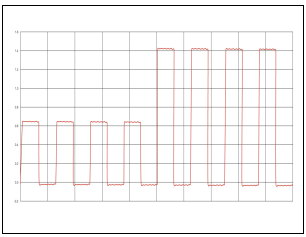
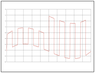
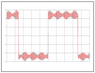
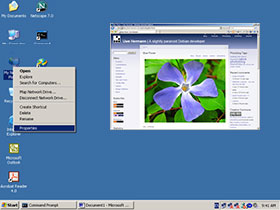
EMI affects both audio and video signals. In audio signals, it obscures low level detail and ambient information. In video signals, the interference distorts the signal and is manifested in different ways. Figure 1 shows an image with no interference. Figure 2 represents a video signal waveform with no interference.

Figure 1: Normal Picture - No Interference

Figure 1: Normal Picture - No Interference

Figure 2: Representation of a Video Signal without Interference

Figure 2: Representation of a Video Signal without Interference

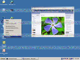
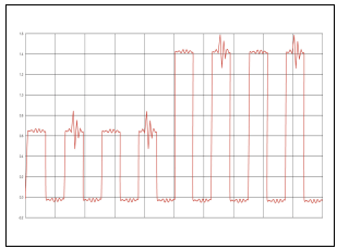
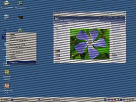
Noise from sources such as air-conditioners, elevator motors, generators etc. is manifested as lines of noise or spots, as shown in Figure 3. This is caused by the electric and magnetic fields generated in the motor as it is running. The larger the motor, the larger the electric and magnetic fields will be. Rapidly turning the motor on and off can also cause interference. Figure 4 shows a video signal waveform with interference from a motor.

Figure 3: Interference Caused by a Motor

Figure 3: Interference Caused by a Motor

Figure 4: Representation of a Video Signal with Interference from a Motor

Figure 4: Representation of a Video Signal with Interference from a Motor

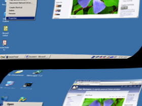
A torn and distorted image as shown in Figure 5 is caused by running the cables in the vicinity of sources of strong magnetic fields such as large power transformers and fluorescent lights. The cables have to be in close proximity (less than 1 foot) of fluorescent lights for interference to occur. Figure 6 depicts a video signal waveform that is affected by a large magnetic field.

Figure 5: Interference Caused by Flourescent Lights

Figure 5: Interference Caused by Flourescent Lights

Figure 6: Representation of a Video Signal with Interference from a Magnetic Field

Figure 6: Representation of a Video Signal with Interference from a Magnetic Field

A visible pattern of interference lines as shown in Figure 7 is the result of interference from sources such as radio transmitters. The radio signal needs to be strong and nearby for it to interfere with the video signal being transmitted on a twisted pair cable. Figure 8 shows a video signal waveform with radio transmitter interference.

Figure 7: Interference Caused by a Radio Transmitter

Figure 7: Interference Caused by a Radio Transmitter

Figure 8: Representation of a Video Signal with Radio Transmitter Interference

Figure 8: Representation of a Video Signal with Radio Transmitter Interference

In a future posting, I will be discussing how shielded twisted pair cabling can help reduce EMI problems.

Posted in Insight | Tagged , , , , | Leave a comment

Environmental Threats to Data Centers, Telecom Switching, and POP sites

Your critical business services can be threatened by a range of environmental factors. In this posting, I will discuss several of these threats and the challenges each poses in data centers, telecom switching sites, and other point-of-presence sites where the equipment is crucial to a company

Posted in Insight | Tagged , , | Leave a comment

View EVIROMUX SEMS Sensor Data as XML

NTI’s Enterprise Server Environment Monitoring System (ENVIROMUX-SEMS-16) provides full configuration via a web interface. NTI provides a fully functional web interface demo.
The Summary page lists all sensors, including their type, description, value, and status.
The value and status parameters for each sensor can also be monitored via an XML feed.
Although the purpose of this feed is to for the SEMS web interface itself to asynchronously update the data on the screen without requiring the user to refresh the page, it can be used by external software to periodically retrieve the data.

The XML feed can be accessed at [IP Address of the SEMS]/sensors.xml.

Here’s a sample XML:

<?xml version='1.0' encoding='ISO-8859-1'?>
<sems>
	<pows>
		<pow_v1>OK</pow_v1>
		<pow_s1>Normal</pow_s1>
	</pows>
	<ints>
		<ints_v1>91.0&amp;#0176F</ints_v1>
		<ints_s1>Normal</ints_s1>
		<ints_v2>22%</ints_v2>
		<ints_s2>Normal</ints_s2>
		<ints_v3>13.5V</ints_v3>
		<ints_s3>&lt;FONT COLOR="red"&gt;Alarm&lt;/FONT&gt;</ints_s3>
	</ints>
	<exts>
		<exts_v1>70.5&amp;#0176F</exts_v1>
		<exts_s1>Normal</exts_s1>
		...
		<exts_v32>33%</exts_v32>
		<exts_s32>Normal</exts_s32>
	</exts>
	<dinp>
		<dinp_v1>Closed</dinp_v1>
		<dinp_s1>Normal</dinp_s1>
		...
		<dinp_v5>Closed</dinp_v5>
		<dinp_s5>Normal</dinp_s5>
	</dinp>
	<rout>
		<rout_v1>Open</rout_v1>
		...
		<rout_v4>Open</rout_v4>
	</rout>
	<ipd>
		<ipd_v1>Responding</ipd_v1>
		<ipd_s1>Normal</ipd_s1>
		<ipd_v2>Responding</ipd_v2>
		<ipd_s2>Normal</ipd_s2>
	</ipd>
	<title>&lt;FONT COLOR="red"&gt;&lt;/FONT&gt;</title>
</sems>

The root node is sems. It contains:

  • pows – power supplies
  • exts – external sensors
  • ints – internal sensors
  • dinp – digital inputs
  • rout – output relays
  • ipd – IP devices
  • title – indicates an overall presence of an alert

Each of the nodes above contains as series of children nodes. Each two of the children nodes correspond to
one sensor as indicated by the ending number. The letter after the underscore indicates whether the node
content is a value (v) or a status (s). Therefore <ints_v1> and <ints_s1> describe the first internal
sensor’s value and status respectively. The only exception are the output relays which only have values, no
status.

Although the SEMS has 16 inputs you’ll notice that the
external sensor count goes up to 32.
This is because some of the physical external sensors are double-function sensors, like the
Temperature/Humidity Sensor which returns
two values and two statuses for each of the parameters it measures. The double-function sensors will act as
two separate sensors (having IDs of e.g. 1 and 2), while the single-function sensors will act as only one
omitting the second set of nodes. Here’s an example:

<exts_v1>70.8&amp;#0176F</exts_v1>
<exts_s1>Normal</exts_s1>
<exts_v2>28%</exts_v2>
<exts_s2>Normal</exts_s2>
<exts_v3>Open</exts_v3>
<exts_s3>Normal</exts_s3>
<exts_v7>73.0&amp;#0176F</exts_v7>
<exts_s7>Normal</exts_s7>

The first two sensors are the Temperature/Humidity Sensor (exts_v1, exts_s1 and exts_v2, exts_s2). The second sensor is the
Infrared Motion Detection sensor,
which occupies IDs 3 and 4. Because it is a single-function sensor the nodes with ID 4 are skipped.

In the example above sensor with ID 3 is followed by sensor with ID 5, therefore we can assume that there’s no
sensor plugged in or configured for port 3. The rule is that for a sensor port P the node IDs are P * 2 – 1 and P * 2. If you
have multiple SEMS connected in a master/slave configuration the sensor node IDs will start with the master and continue
with each following slave, so the formula for slave S (for master S will be 0) and port N will be S * 32 + P * 2 – 1 and S * 32 + P * 2.

The last node, title, indicates whether there are any sensor alerts present. If there are no alerts it will contain a only &lt;FONT COLOR=”red”&gt;&lt;/FONT&gt;, otherwise it will also contain Sensor Alerts Present (i.e. &lt;FONT COLOR=”red”&gt;Sensor Alerts Present&lt;/FONT&gt;).

A few notes:

  • The degree sign (
Posted in Application Note | Tagged , , , | Leave a comment